Contact Person: Mr.Li
Mobile: +86-18509252400
Wechat: 18509252400
Email: info@mudsolidscontrol.com
Address: No.2 Huochang Road, Yangling District,Xianyang City, Shaanxi Province, China
Nearly every mud tank enquiry opens with a volume. How many cubic metres of mud tank capacity does this rig need, or how many barrels, depending on who wrote the programme. Contractors expect a number back.
We build the tanks, and we cannot give you one from depth. Two rigs going to the same total depth can want surface volumes a compartment apart, because hole programme and pump output move the number further than the depth band does. A metres-to-cubic-metres table is easy to find. It is quoted against one input and hoping the rest holds.
Sizing runs on the hole programme and the peak pump rate. Everything below follows from those two.
What sets the working volume
Where the total goes
The mud tank capacity on the quote is not the capacity you pump from
Why the compartment layout decides whether that volume works
What limits the configuration
Hole sections come first. Hole diameter, section length and where the casing shoes land decide how much fluid the surface system carries at any depth, and that inventory is what the compartments can contain and deliver. Two wells at one TD with different intermediate sections need two different tanks.
Pump output comes second, and it is the one that gets missed. Compartments have to keep pace with the peak planned rate, not with what the rig averages across a week. Where they fall behind, the symptom is not a level problem. Sand content climbs, and dilution gets added to cover it. The tank is built by then.
Mud weight changes what the tank carries rather than how much it holds. Maximum density over the programme sets the fluid load on the structure and the supports, and it sets the agitation duty. Hand over the highest density you expect, not the one you spud in with.
Four lines, sized in that order.
Mud tank working volume and active system inventory are not the same figure, and enquiries run them together constantly. Working volume is what the compartments can deliver to the suction at the working level. Active inventory is larger, because surface lines, pumps, treating equipment and the hole itself hold circulating fluid too. Suppliers quote the first. The rig runs on the second. Say which you mean on the enquiry, and state the level you are quoting at.
Reserve volume is not a percentage anybody can hand you. It depends on how exposed you are to a loss zone, how far the mud plant is, and whether stopping to build mud is affordable on your day rate. A rig working a known formation with a plant on location runs lean. The same rig in a frontier area does not.
Mixing and pill capacity is the line most often left off. A system without a dedicated mixing compartment borrows one at the moment it weights up, so the crew waits or an active compartment drops out of service exactly when the programme needs it. Borrowing costs nothing on a drawing. On a delivered tank there is no spare to borrow from.
The trip tank is sized against what the crew has to read: measurement resolution, how the level is monitored, and what the well control procedure asks for. The largest tank that fits the skid improves none of those.
State the units as well. Capacity gets quoted in cubic metres or in barrels, and 1 m³ is about 6.29 bbl. Mixing the two inside one enquiry is a reliable way to lose a compartment. Pick one, print it on the enquiry, hold every supplier to it.
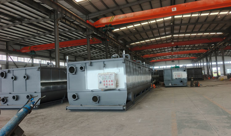
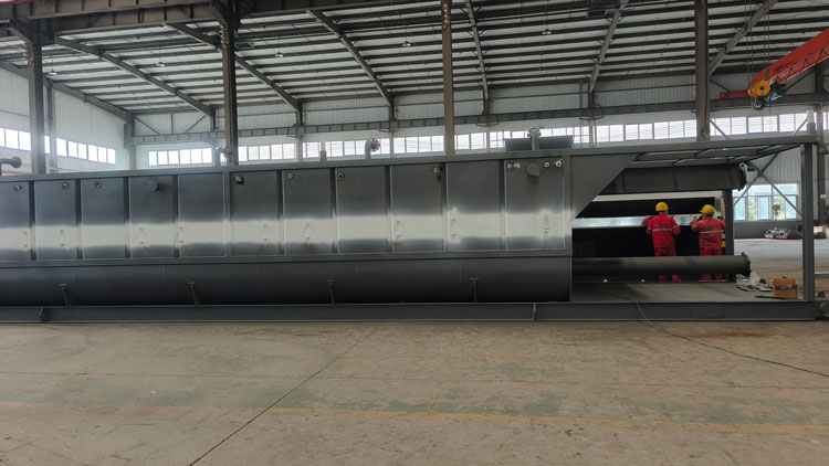
A capacity range can be useful as a starting point, but it should not replace project-based sizing.
The following ranges are only general references for land drilling applications:
| Rig class | Total tank volume | Same figure in barrels | Modules usually quoted |
| Workover rig | 40-60 m³ | 250-380 bbl | 1-2 |
| 350-650 HP (ZJ20) | 60-120 m³ | 380-755 bbl | 2-4 |
| 750 HP (ZJ30) | 120-180 m³ | 755-1,130 bbl | 3-4 |
| 1000 HP (ZJ40) | 140-300 m³ | 880-1,890 bbl | 4-6 |
| 1500 HP (ZJ50) | 200-580 m³ | 1,260-3,650 bbl | 5-9 |
| 2000 HP (ZJ70) | 370-775 m³ | 2,330-4,870 bbl | 6-12 |
| 3000 HP (ZJ90) | 900-1,000 m³ | 5,660-6,290 bbl | 13-14 |
These figures represent usable working volume, not simply the steel tank size.
The final mud tank capacity depends on the drilling programme, circulation rate, reserve requirements, mud properties and the complete solids control system arrangement.
Buyers send competing quotes to be matched more often than they send a drilling programme. The figure on the summary page is the only thing three proposals share, and it rarely means the same thing in any two of them. One is the steel box measured to the rim. One is volume to the overflow line. One is what the suction can draw at the working level. You are comparing three different systems, and nothing on the paperwork shows it.
What eats the difference is ordinary. Freeboard, and how much of it depends on the level each supplier assumed. Bracing, bulkheads and agitator shafts. On a sloped bottom, the space under the suction nozzle, which is volume you can see and cannot pump from. Solids between cleanouts, which take a little more each week and get logged by nobody.
Ask each supplier for four figures in writing: nominal capacity, usable working volume at a stated working level, usable volume of each compartment, and the level itself with the method behind the quoted number. Leave it off the enquiry and whoever quotes has to assume one, and the assumption lands in the price, as steel you did not need or volume you did not get.
The compartment arrangement decides whether fluid gets treated before it reaches the suction.
Short-circuiting is what nobody specifies against. A weir set at the wrong height, or a return line discharging into the wrong compartment, and fresh return reaches clean suction before it has been through the shakers, the degasser or the cones. It is easy to build in and expensive to correct, because by the time it is diagnosed the compartments are welded, coated and sitting under a running shaker. Check the weir elevations and the return line positions on the drawing, before the tank is built.
Which compartment the degasser and the centrifuge draw from matters more than it looks on paper. Pull from the wrong one and you spend weeks chasing a separation problem that started as a plumbing problem.
A bigger tank does not fix a bad flow path. In a complete solids control system, tank volume and compartment design work together with each separation device. A good shaker or centrifuge cannot perform well if the tank flow path sends untreated mud back to the suction.
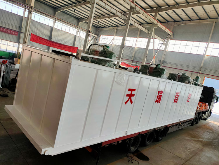
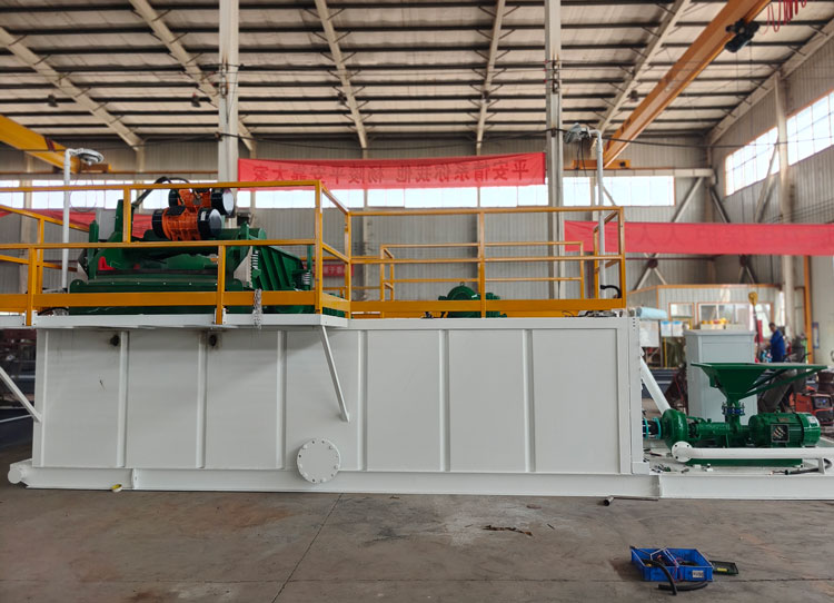
Transport sets the module count. A contractor asking how many mud tanks a rig needs is asking two questions at once: how much volume the programme requires, and how many pieces the route will let him move it in.
On land, a single mud tank module is bounded by the road envelope on the longest leg of the move, and that envelope changes with escort and permit requirements. Every extra module adds a manifold, a set of connections and a rig-up task, so the count is a cost line before it is a process decision. Offshore, deck load and lift capacity do the same job, with the harder constraint that a module cannot be added later if the deck will not take it.
What catches layouts out is filled weight. A compartment full of heavy mud carries several times the mass of the empty steel, and the load that has to be checked is the fluid plus the tank plus everything mounted on it. Layouts get reworked at this point, because the check was run against the empty tank.
That equipment list belongs on the enquiry too. Shakers, degasser, desander, desilter, centrifuge, pumps, hoppers. Mounting positions change compartment sizing, and a deck layout agreed late is a layout agreed twice.
If you are replacing a system, say what was wrong with the old one before proposing a size. Short of working volume, no reserve worth the name, compartments that fight each other, or a skid that is awkward to move. Naming the failure is what stops the replacement from reproducing it.

Address: No.2 Huochang Road, Yangling District,Xianyang City, Shaanxi Province, China
Tel: +86-18509252400
Wechat: 18509252400
Email: info@mudsolidscontrol.com
Contact: Mr.Li
 +86-18509252400